Vacuum Forming Model Parts
In September 2016 I presented a clinic on this project at the National Narrow Gauge Convention in Augusta, Maine. At some future date, after I finish my new workshop, I expect to add information on forming more complex pieces such as clerestory roofs. Left click on the photos to enlarge them to full screen.
For more than 50 years I have been making scale line drawings of the buildings and equipment of the two-foot gauge railroads that once ran in several locations in Maine. Occasionally I’ve built scale models of them. Many of the passenger cars on these railroads had simple curved roofs that were easy to build but difficult to model because of the compound curves at the corners.

I had long thought about vacuum-forming those compound curve roofs, and a few years ago experimented with a simple rig for doing that. When I finally got around to doing it I found it was easier than I expected. This page describes how I made my vacuum former and how my roofs came out.
The process is more accurately called thermo-forming. It simply involves reconfiguring a material that softens when heated, is easily molded over a form, and permanently holds its new shape. The vacuum is used to draw the heat-softened material tight to the form.
Six elements are needed for vacuum forming:
1. a mold form in the shape of the inside of the part to be molded;
2. a sheet of thermoplastic material to mold;
3. a heat-proof frame to hold material you will be molding;
4. an airtight space to contain the vacuum;
5. a heat source to soften the molding material; and
6. a vacuum source to evacuate the airtight space.
 Commercial vacuum molding machines, which can cost tens of thousands of dollars, include built-in heat and vacuum sources and draw the material tightly against the mold plug, using two or more increasingly powerful stages of vacuum. This compact machine will fit into a home shop but costs about six thousand dollars.
Or you can go to eBay and buy a more basic unit built to any size you specify for about $100.
 There are two serious flaws with this design, however. First, even with interior baffles, it contains a large volume of air that has to be evacuated before it begins to draw down the plastic, giving the plastic more time to cool and become less moldable. Second, the tiny holes in the surface plate restrict air flow, thereby slowing the molding process. As you will see, the space that needs to be evacuated can be very thin, and there is no need to direct or disperse the vacuum across the plate.
My Simple Vacuum Former
My simple machine uses a kitchen oven as a heat source, a household vacuum cleaner for a vacuum source, and mold forms designed so that a tight draw is not necessary.
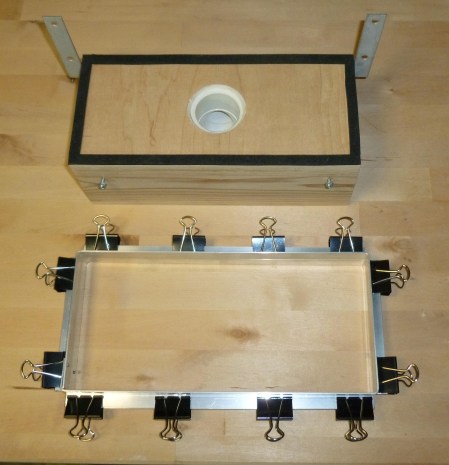
This simplest type of vacuum formers is a flat board with a hole that fits tightly around the vacuum source, sponge rubber weather stripping around the perimeter, and a removable frame to hold the molding material. In this case, the flat board is 1/2″ furniture-grade birch plywood glued to a simple frame of 1″ x 4″ cedar that I had on hand.
The box base is 1/4″ smaller than the inside of the aluminum frame, in order to allow the frame to slip easily over the box. The weather stripping is only 1/8″ thick by 3/8″ wide, so the area to be evacuated is only the thickness of the weather stripping. Note that it is important to use rubber weather stripping as it is more tolerant of heat than other materials. The metal screen keeps the plastic from being drawn into the vacuum hole and distorting the part being molded.
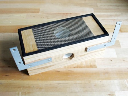
The box frame supports the molding board and encloses a PVC pipe elbow that fits the vacuum hose tightly and allows the hose to be attached to the side of the box. The elbow is a snug – but not forced – fit on my vacuum hose, and attached with silicone sealant that also seals the space to be evacuated. The opening on top is slightly larger than the hose connection, but that is not important. It should not be smaller, however.

Two four-inch angle irons serve to guide the frame over former. Some scraps of 4mm plywood space the angles from the box to provide room for the aluminum frame to fit around the box. Two screws on the opposite side hold the empty frame level, although they are not necessary when there is plastic in the frame.
The frame is fabricated from 1/2″ x 3/4″ aluminum angle stock available at any hardware store. I cut the 1/2″ web at distances that are an inch less than the size of the material to be molded and then bent each corner 90 degrees. In this case, I wanted to use standard 6″ x 12″ Evergreen Models styrene sheets, so the inside of the frame is 5″ x 11″. The open corners of the frame halves are folded over and riveted with a cut-off aluminum nail.
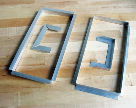
The frame halves are then held together with medium size binder clips that pinch the mold material between the frame halves. Set the clips about two inches apart to keep the plastic sheet taut. Avoid clips that have rubber or plastic coatings, as they may not be heat resistant.
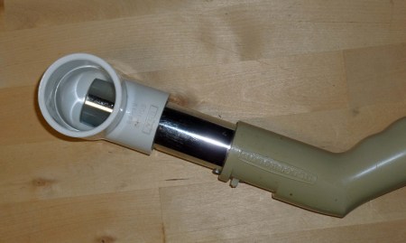
This shot shows how the PVC angle fits snugly on the end of the vacuum hose. In this case, the vacuum is an Electrolux that I bought new in 1963. I installed a clean bag before using it, as any dust in the bag will reduce the amount of vacuum available.
The Mold Form

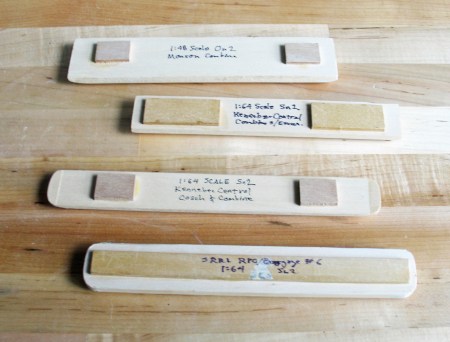
Making the mold form is not difficult, but it is the most exacting step in the process. This form is for an Sn2 (1:64 scale) roof for a Kennebec Central RR passenger car or combine. It is the first one I made. This one is made from 3/8″ thick basswood, but I have had better results with subsequent molds using 1/2″ basswood.
First, I cut the blank to size with a 4″ Dremel table saw, then I carefully sand it to shape with 60 grit paper, followed by 120 grit paper. It helps to make a cardboard template of the cross-section shape and the end section shape, but I still do most of it by eye.
If the roof is trimmed parallel to the sides, as on the left of this sketch, the form should be cut to the full outside width, while the height must be reduced by the thickness of the material being molded. If the roof is trimmed perpendicular to the sides, as on the right of this sketch, the form should be cut the inside dimension in both width and height.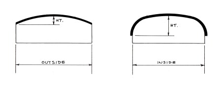
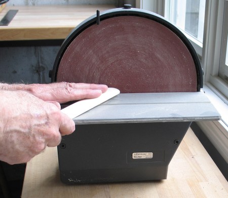
I rough out the form blank using a power sander, then finish it to final size and shape with a hand sanding block. This process is easier than it sounds, and takes very little time.
Sometimes I tape a sheet of sandpaper to the bench and run the form back and forth over it.
Here are four different mold forms. I find by adding a rounded piece of wood to the ends of the form reduces the effect of the plastic creasing at the corners.
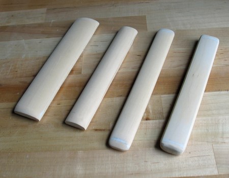
All of the mold forms have scraps of 1/8″ thick wood glued to the underside to lift them above the platform. This allows air to move freely under the plug and assures that the styrene will follow the full shape of the plug with no need for secondary vacuum.
Molding the Part
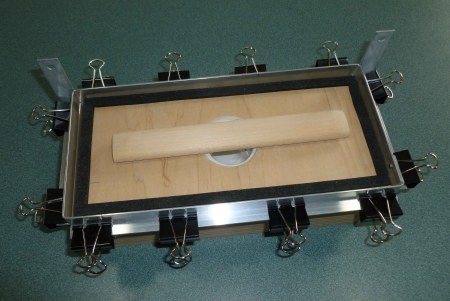
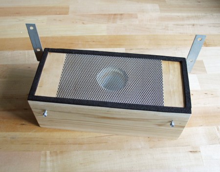
Here the mold form for a passenger car roof is in place. I later added a piece of expanded metal screen over the vacuum hole to keep the styrene from being drawn into the hole and distorting the finished piece.

The plastic sheet is clamped between the two halves of the frame using binder clips. Note that the corners need to be clipped off so they do not interfere with the angle iron guides. I just cut a one-inch angle off each corner. It does not matter if some of the cut off area is exposed inside the frame, as long as you get full contact with the weather stripping. The color of the material also does not matter. Black or white, either work as well. I haven’t tried clear, but it should work as well too.
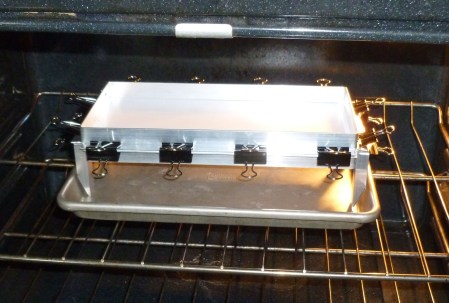
To soften the styrene, I place the aluminum frame in a kitchen oven preheated to 350 degrees Fahrenheit. Note the legs made from scraps of aluminum angle to raise the frame above the rack. They are held in place by the binder clips. An inexpensive baking tray under the frame helps to distribute the heat evenly and would prevent a mess if I inadvertently leave the plastic in the oven too long.
After placing it in the oven, I set a kitchen timer. Five minutes seems about right for 0.030″ thick styrene. For 0.040″ material I leave it in another minute; for 0.020″ material, I take it out a minute sooner. I have not tried thicker material, and expect that it would need a stronger vacuum source. You may have heard that styrene softens at 200 to 250 degrees. I experimented with several combinations of temperature and time, and found that 350 degrees works best. At lower temperatures, the styrene takes too long to soften.
When you put the styrene in the oven it almost immediately gets wavy, then it draws taut before slowly sagging a quarter inch or so, where it stays until taken out of the oven. About 30 seconds before the timer goes off, I shut off the oven, turn on the vacuum, and put on a pair of heat-proof mitts. Remember that the frame is now 350 degrees.
Using the heat-proof mitts, quickly remove the frame from the oven, carefully align it with the angle guides, and press it down firmly over the mold. The molding process happens in a flash. You then shut off the vacuum so it does not stress the motor, and wait for the frame to cool down enough to touch, which takes only a few minutes.
At the narrow gauge convention I showed a five-second video of the molding process that elicited gasps from the audience because the process happens in the blink of an eye. I cannot show it here, though, because my basic WordPress subscription does not support videos. Here is what the molded piece looks like:

If you get the frame too close to the mold before fully aligning it with the angle irons, the vacuum will draw the plastic down prematurely. If the pattern is still close to centered, like the one on the right below, the part will still be usable. If it is too far off-center, like the one on the left below, it will not draw tight enough and must be scrapped.

Trimming the Part to Shape
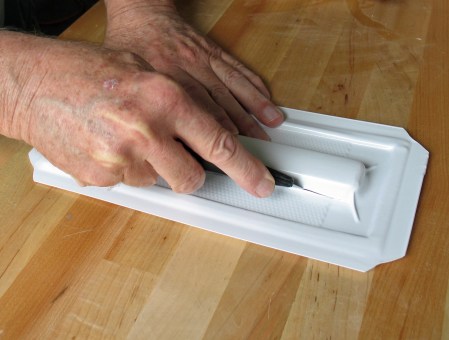
First, I cut the molded part roughly near the bottom of the mold form. Note that the form is still in place, which helps keep the part from distorting while being cut.
Then I trim it close to – but not right at – the final size. I use a sanding block to bring it to final size.
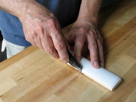
Using a miter box and razor saw, I score the end close to final dimension. I then either snap the end off and finish it to size with a sanding block, or cut it to size with a single-edged razor blade.

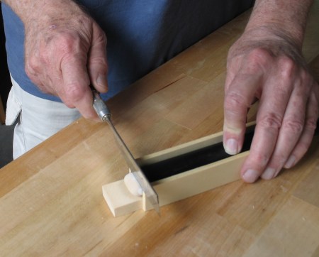
If I’m making multiple copies of a particular roof, I’ll put together a custom miter box to the exact width of the roof. Then I use a razor blade – not the saw shown in this photo – to cut the end to size.
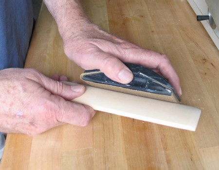
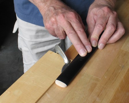
For roof pieces with a horizontal edge, I use a different technique. As shown here, I clamp a curved knife blade, shimmed to the proper height, to the workbench and run the roof piece – still on the mold form – along the knife. It takes several passes to cut through, but don’t force it, as you may distort the plastic.
And that’s all there is too it. I’m sure there are more and better ways to do this, and many more items that could be made with this process. I encourage you to try it, as it’s great fun and requires very little investment in time or materials. Let me know if you come up with new ideas or better methods.
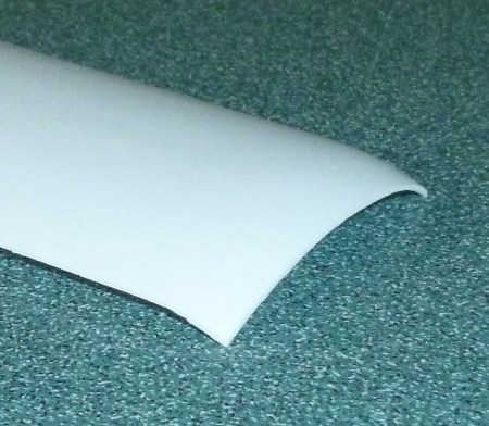
This was one of my first pieces, a 1:48 scale roof for the Monson RR combine. It is molded from 0.040″ thick styrene, which is hard to cut and sand to shape. You can see where I knicked it near the corner. With practice I’ve gotten better at it, but I find that 0.030″ stock is much easier to work with.
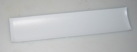
Here is another On2 Monson combine roof. This one is made from scribed siding, simulating 2-1/2″ roof boards on the underside. The scribed material costs three times as much as the plain, and it is even harder to trim because the knife wants to follow the scribed line.

August 14, 2013 at 8:02 pm |
Nicely done Wes — thanks for sharing.
October 13, 2015 at 1:45 pm |
this will be a must see for me at the Augusta 2016 NG Convention
September 18, 2016 at 1:31 am |
looks like I might have to try that. Paul R.
October 11, 2016 at 7:42 pm |
Thanks! There was just too much going on at the convention to make all the clinics. Hated to miss this one and really appreciate your posting the information.